3D Printable 1986 Z31 Door Lock Mechanism
A 3D printable redesign of the easily broken Z31 door latch mechanism.
Have you ever been stuck in your z31 because your door lock isn’t unlocking? I have, and climbing out of the driver’s seat to get to the passenger door without getting impaled by the shifter really sucked.
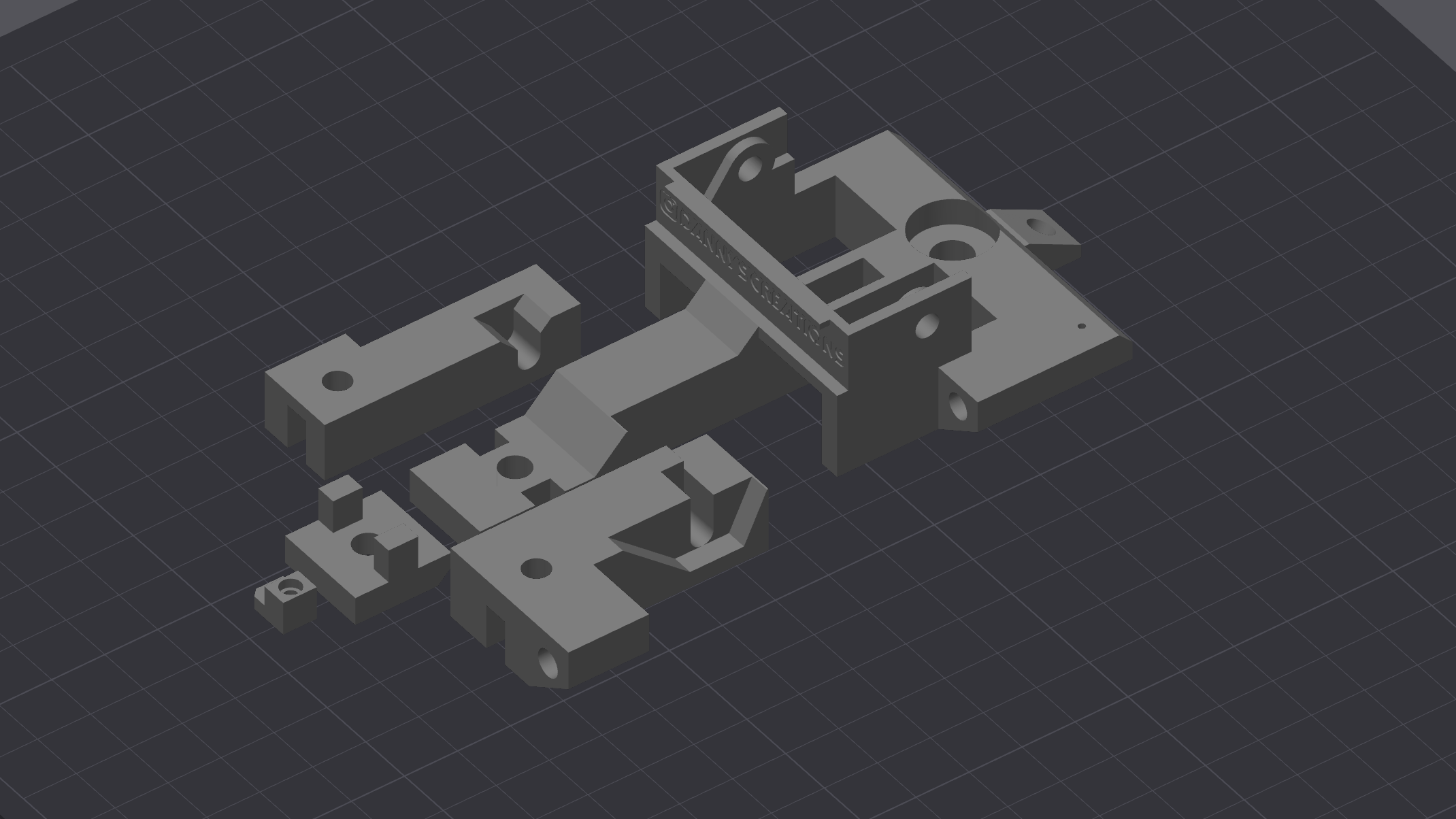
That is where this design comes in. The original OEM door latch mechanism relied on very thin plastic to actuate the door latch and lock. Since the Z31 is now 40 years old, that plastic is ready to break at the worst time possible. This design significantly beefs up the sliders that actuates the lock and latch of the doors, while still utilizing most of the OEM parts to keep that original interior look.
What You Need
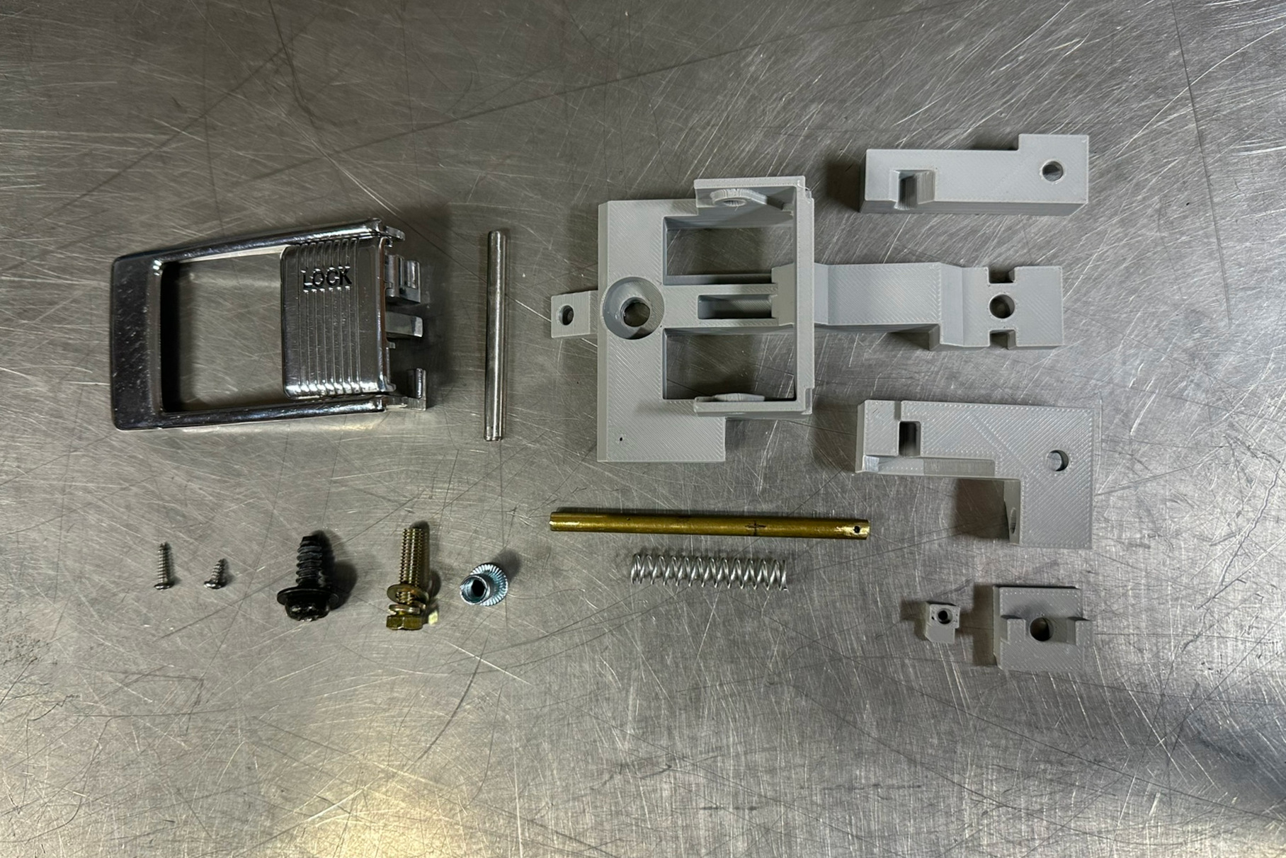
| Parts List |
|---|
| M5x0.8 20mm Bolt with Washer and Lock Washer |
| M5x0.8 Rivnut |
| M2.2 6mm Screw |
| M2 10mm Screw |
| 3 Inches of 3/16 Round Brass Stock |
| 35mm Spring 7mm in Diameter |
| OEM Mounting Screw |
| OEM Slotted Spring Pin |
| OEM Latch and Lock Actuators |
I ended up finding the spring that I used at ACE Hardware. They have a pretty big selection, and they are all pretty cheap, so I bought several and just used the one that had the best action.
3D Printing
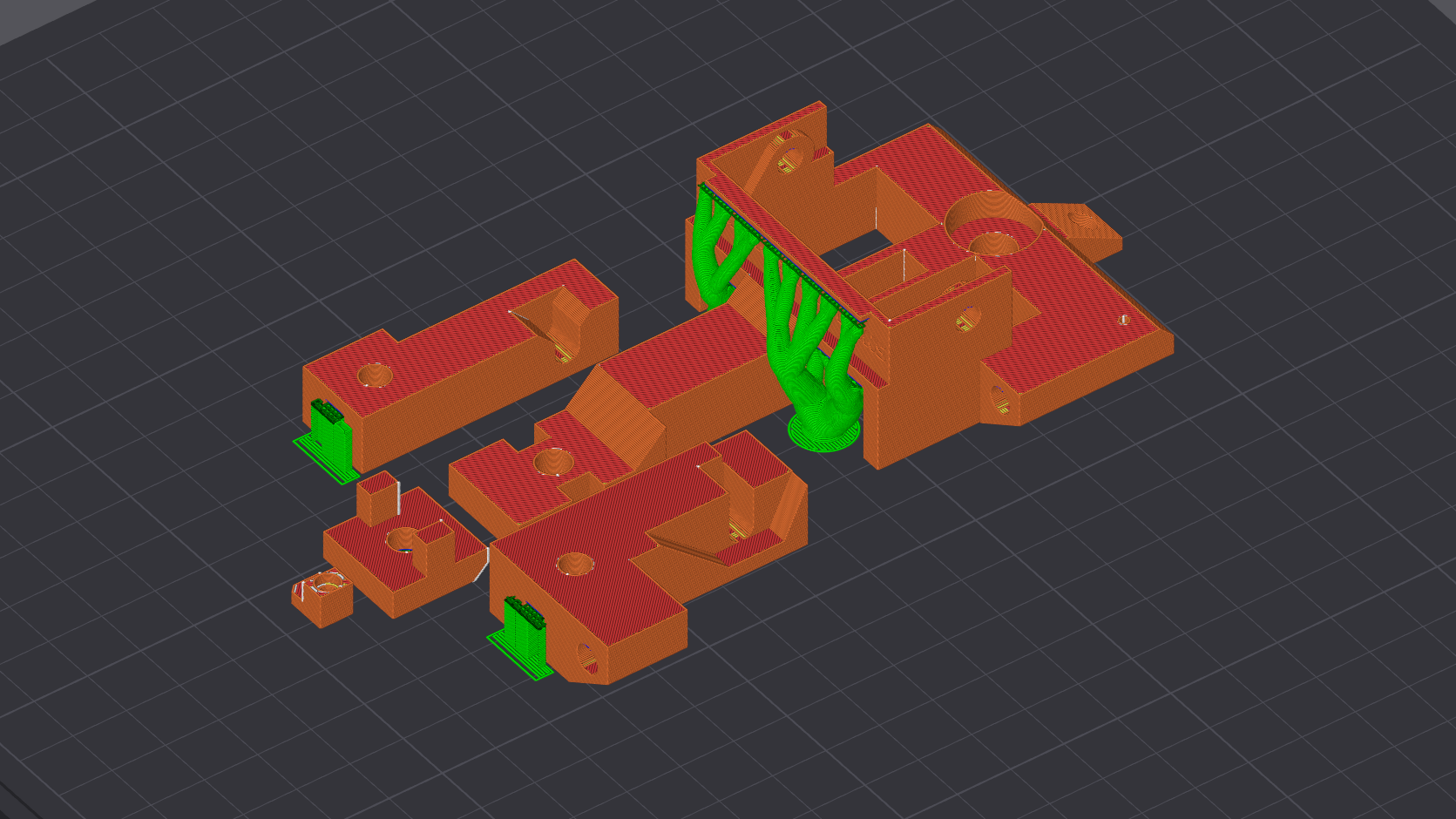
I recommend 3D printing this design in ABS at a minimum. However, it wouldn’t be a bad idea to use an even higher temp filament if you can. Since this part is critical to being able to exit the vehicle, I wouldn’t take any chances with a filament such as PETG. For my print, I used a wall thickness of 4 loops to increase the rigidity of the base print around the boltholes. The sliders, spacer and aligner were all printed with 100% infill since those parts need as much structural integrity as possible.
I set the slicer to only print supports that touch the bed and then manually added the extra supports to the overhang on the base part. The support Z gap was set to 0.05mm, which worked decently well with my printer. I had to separate the supports with a razer blade, but that helped keep the part dimensionally accurate.
Assembly
First you will want to drill out the holes that the round bar stock interfaces with, since the holes will likely not be perfectly smooth or round directly off the printer.
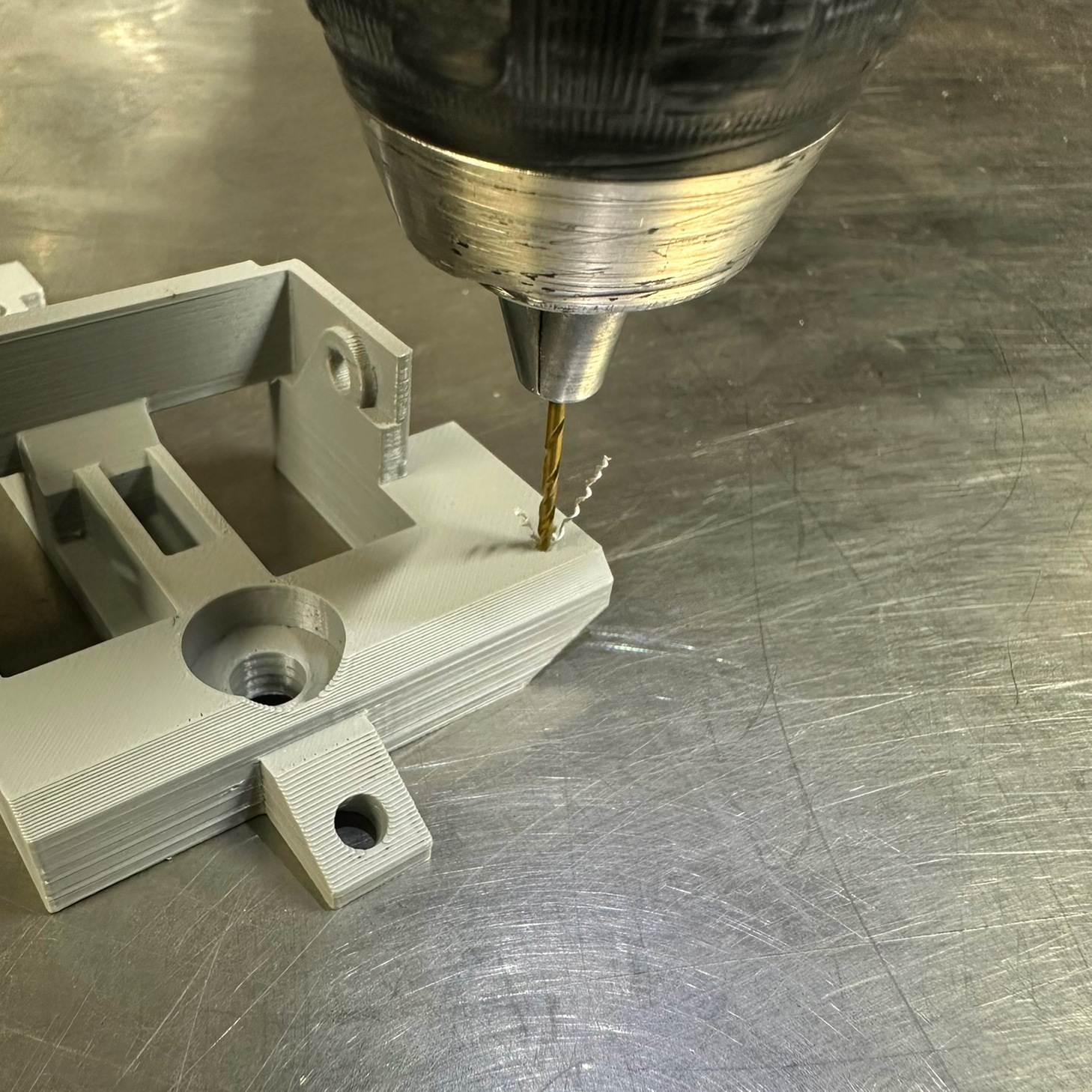
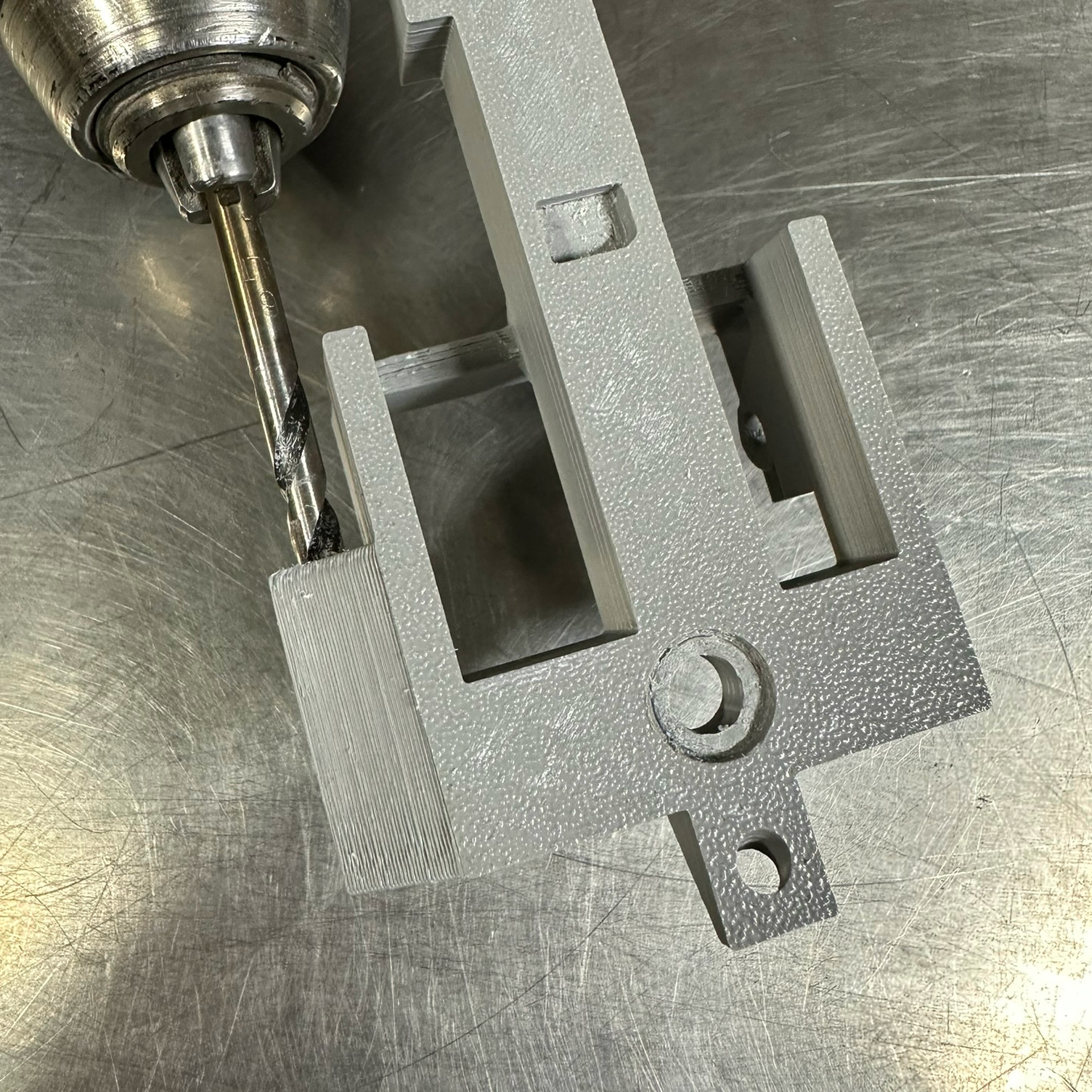
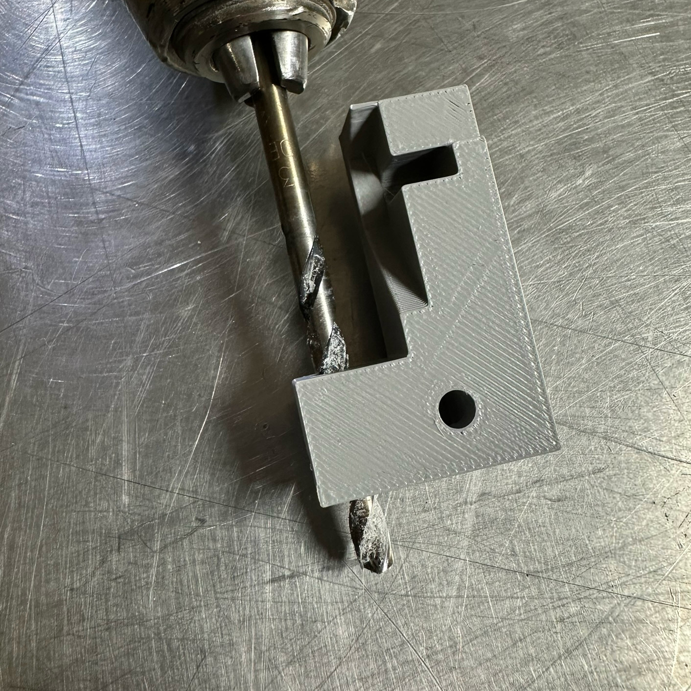
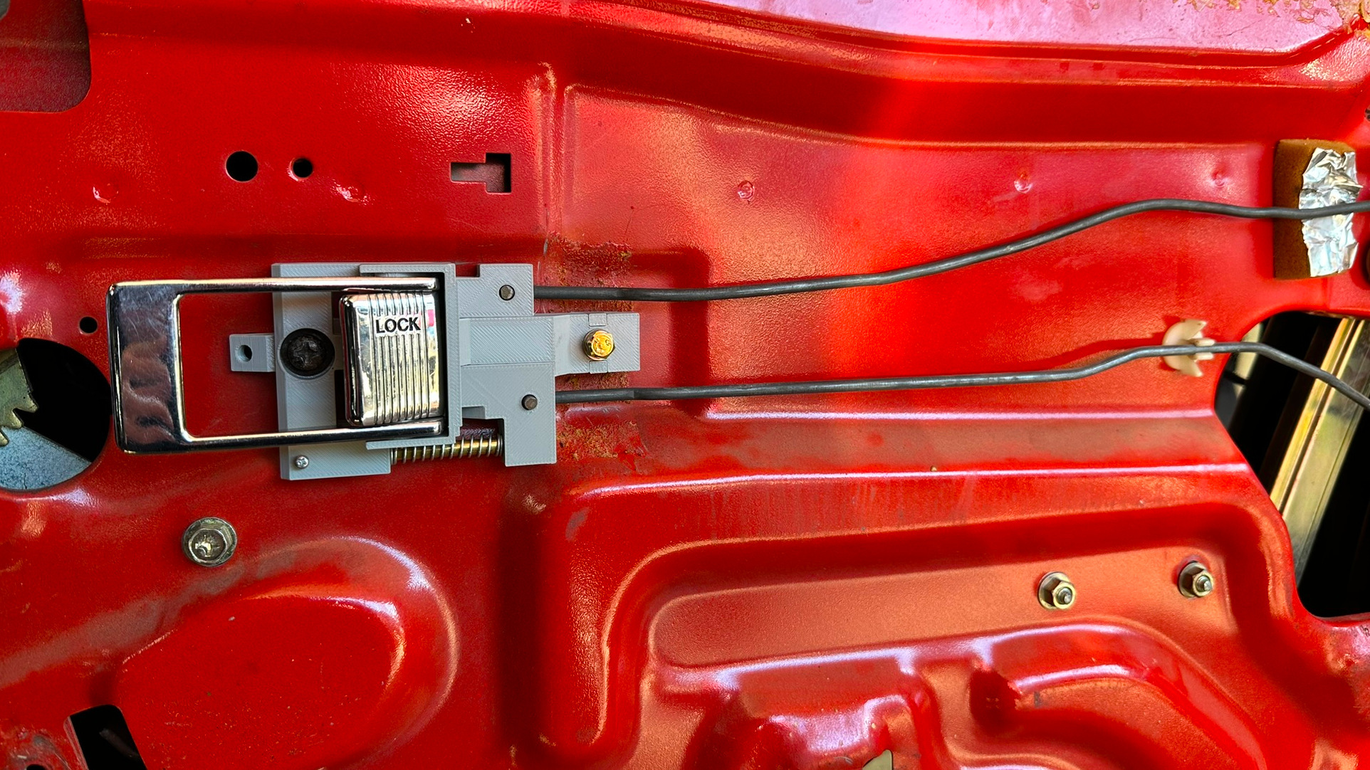
Next, you will need to drill a hole through the end of the brass bar stock that lines up with the setscrew hole on the base part. I made a mark on the bar stock to indicate how far to push it into the print and get the alignment correct for the setscrew since it’s hard to tell once the bar is inserted. After inserting the brass bar through the slider, through the spring, and into the part, I used the M2.2 screw for a setscrew to ensure the brass bar wouldn’t back out.
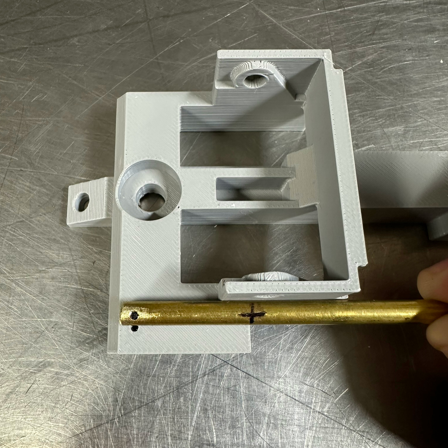
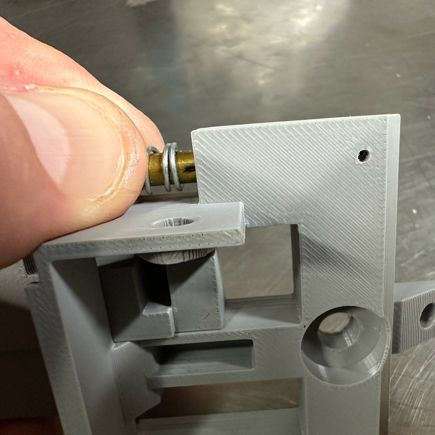
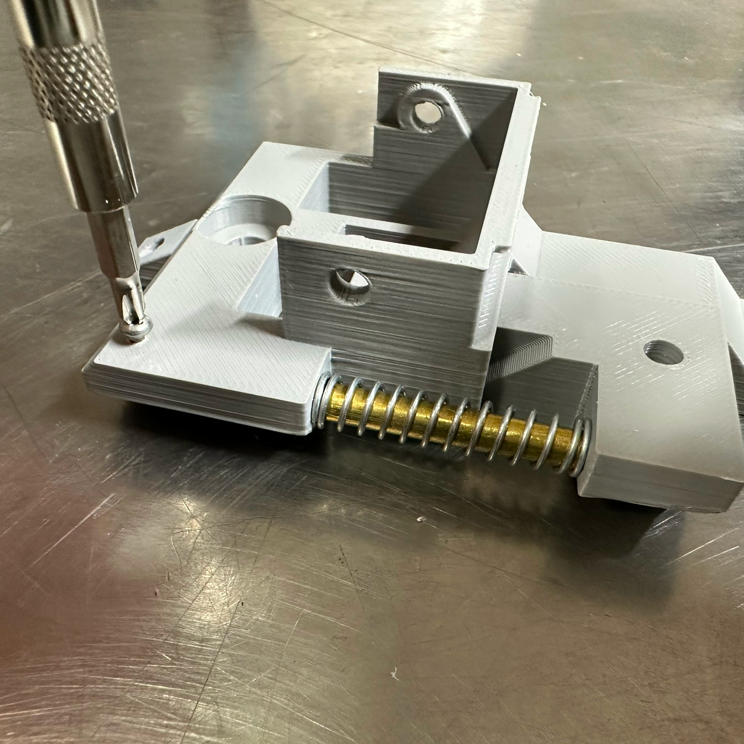
The next thing is to install the alignment piece on the bottom of the base part using the M2 screw. This alignment piece will make it easier to get the correct placement when you install the assembly on the door. After that, press the OEM slotted spring pin through the lock and latch actuators.

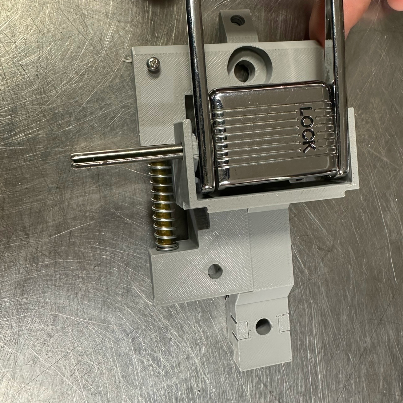
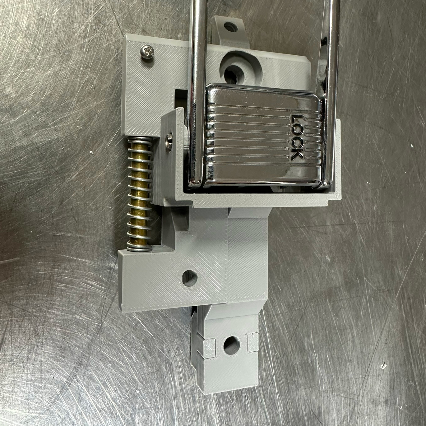
Installation
Position the assembly on the door using the OEM screw. The alignment piece on the rear of the assembly should make it super easy to get the exact position of the OEM part. Mark the center forward piece’s hole so you will know where to install the rivnut. I used a drill bit with the same diameter of the forward hole to mark mine. After that, remove the assembly and drill the rivnut hole. Then install the rivnut.
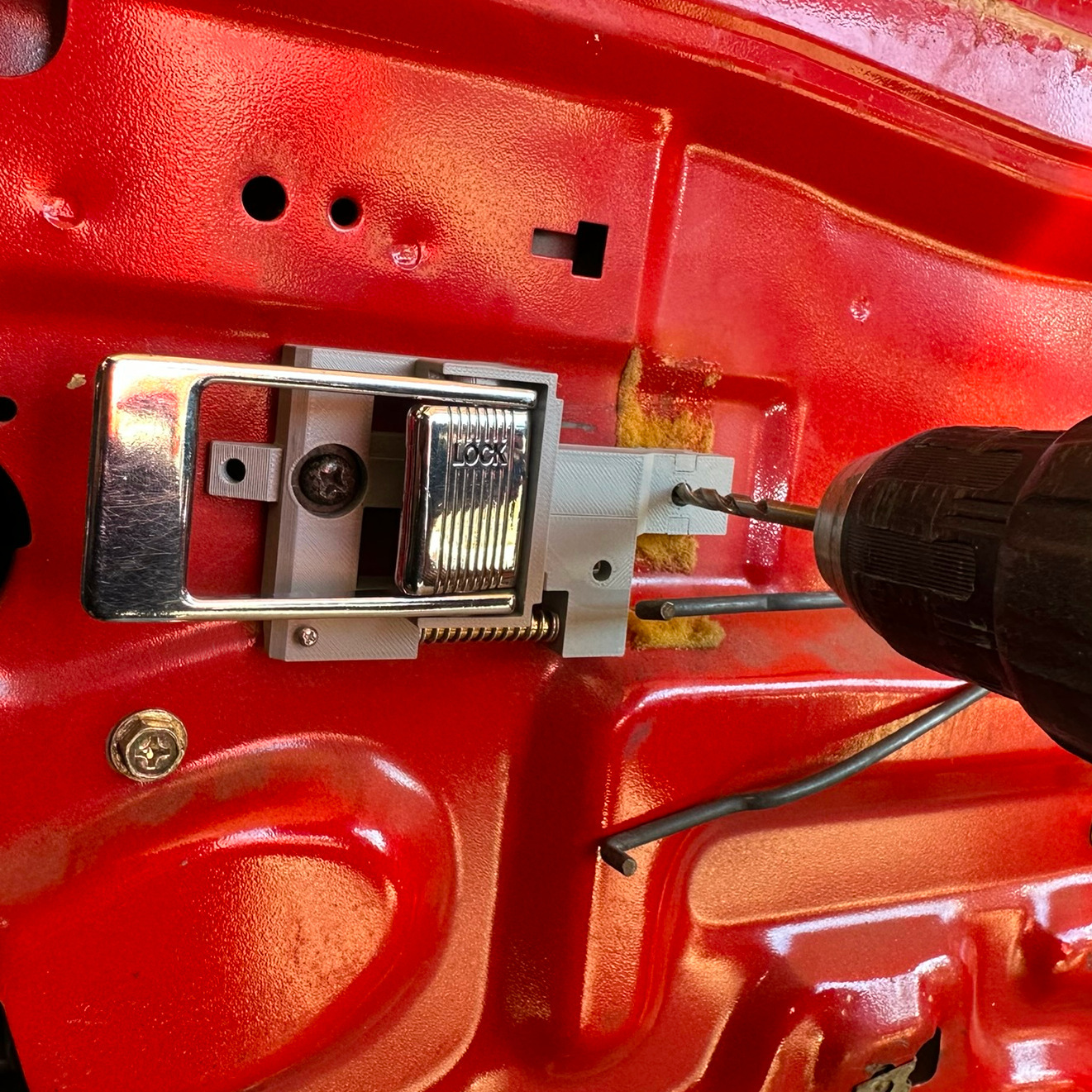
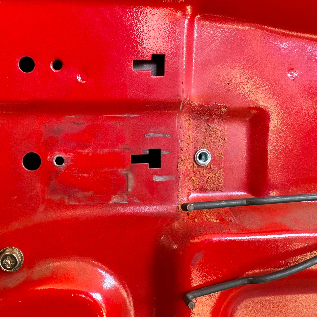
That’s basically it! If the lock doesn’t actuate correctly, you may need to slightly tweak the angle of the actuator rods on the door.
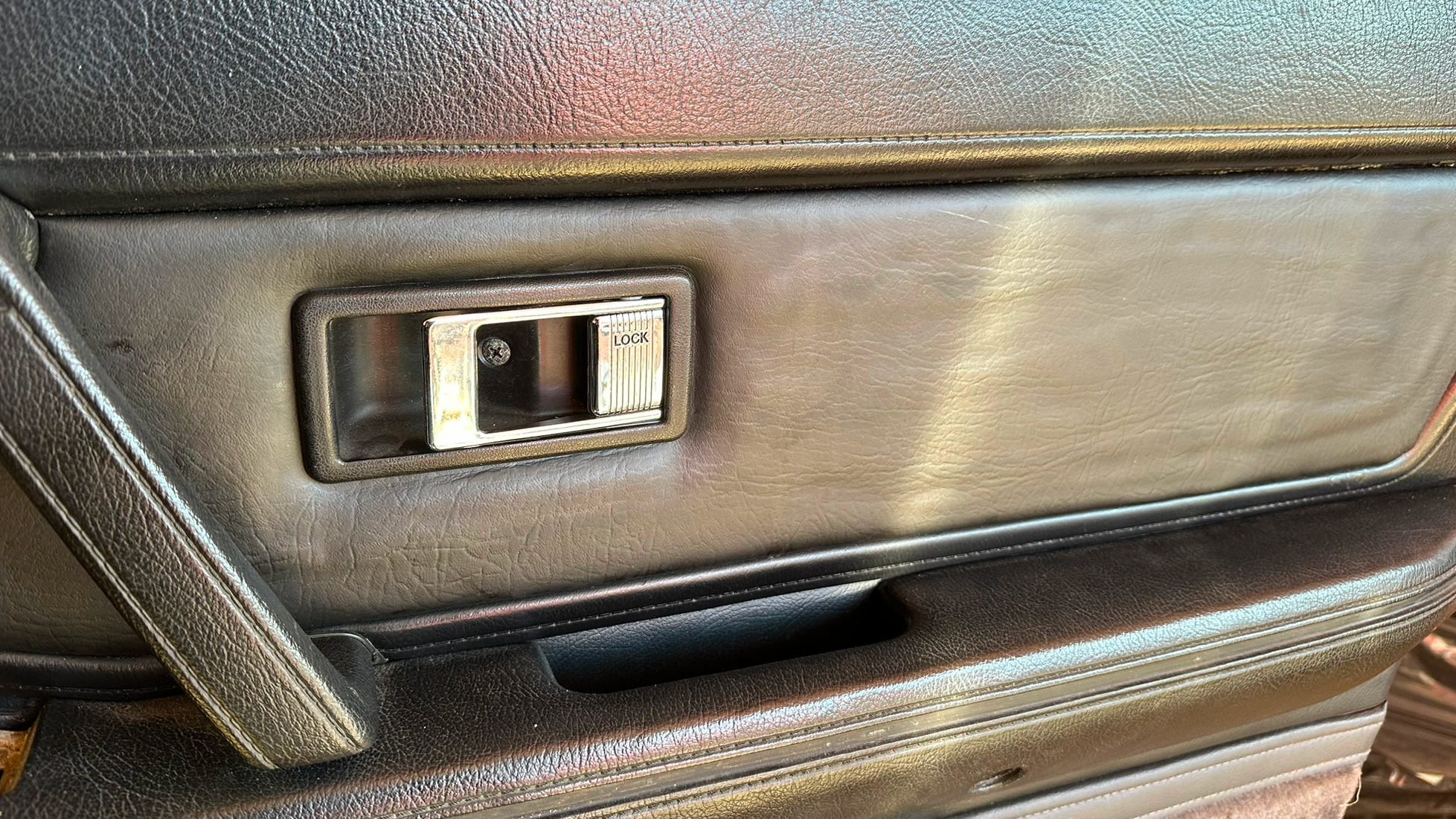
The files are uploaded to thingiverse and are free for anyone to use or improve.